Accessories:External Filters: Difference between revisions
imported>Beastadmin No edit summary |
imported>Dl4mea |
||
| (10 intermediate revisions by 2 users not shown) | |||
| Line 1: | Line 1: | ||
==The Filters== | ==The Filters== | ||
{| class="wikitable" | {| class="wikitable" | ||
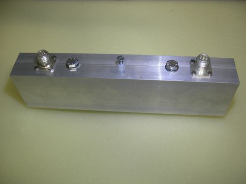
|[[File:1090MHz-3Kreis-Filter-03.jpg|500px|1090 MHz 3 | |[[File:1090MHz-3Kreis-Filter-03.jpg|500px|thumb|1090 MHz 3 Pole Filter (with two N female connectors)]] | ||
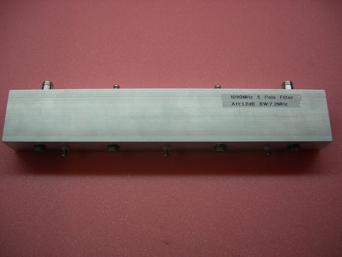
| | |[[File:5pole filter-4-resized.jpg|500px|thumb|1090 MHz 5 Pole Filter]] | ||
| | |||
| | |||
| | |||
|- | |- | ||
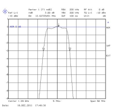
|<ins>Technical data:</ins><br>passband attenuation: 0.5 dB<br>-3 dB bandwidth: 13.5 MHz | |<ins>Technical data:</ins><br>passband attenuation: 0.5 dB<br>-3 dB bandwidth: 13.5 MHz | ||
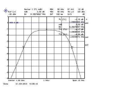
|<ins>Technical data:</ins><br>passband attenuation: 1. | |<ins>Technical data:</ins><br>passband attenuation: 1.2 dB<br>-3 dB bandwidth: 6.4 MHz | ||
|} | |} | ||
| Line 31: | Line 21: | ||
Mode-S Beast with 5 pole filter: to be confirmed with next build | Mode-S Beast with 5 pole filter: to be confirmed with next build | ||
TODO CALCULATOR | TODO ADD CALCULATOR SCRIPT | ||
This calculation was created by my friend Luis Cupido, CT1DMK. Thanks, Luis! | This calculation was created by my friend Luis Cupido, CT1DMK. Thanks, Luis! | ||
| Line 41: | Line 31: | ||
{| class="wikitable" | {| class="wikitable" | ||
|[[File:3pole-narrow. | |[[File:3pole-narrow.jpg|400px|The 3 pole passband measured with R&S FSEA30]] | ||
|- | |- | ||
|''The 3 pole passband measured with R&S FSEA30'' | |''The 3 pole passband measured with R&S FSEA30'' | ||
| Line 47: | Line 37: | ||
{| class="wikitable" | {| class="wikitable" | ||
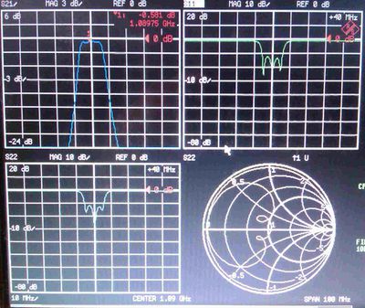
|[[File:3pole-vna-02.jpg| | |[[File:3pole-vna-02.jpg|400px|Filter Measurements with a R&S ZVR VNA]] | ||
|[[File:3pole-s11b.jpg|400px|S11 and S22 with my own FSEA30 and a directional coupler]] | |||
|- | |- | ||
|''Filter Measurements with a R&S ZVR VNA'' | |''Filter Measurements with a R&S ZVR VNA'' | ||
|''As an experiment, I also measured the S11 and S22 with my own FSEA30 and a directional coupler, and I got the same values as with the VNA with a very good reproduction'' | |||
|} | |} | ||
==Measurements of the 5 Pole Filter== | |||
These are the measurements of the 5 pole filter. The few devices that . | |||
[[File: | {| class="wikitable" | ||
|[[File:5pole-narrow.jpg|400px|The 3 pole passband measured with R&S FSEA30 and tracking generator]] | |||
|[[File:5pole-wide.jpg|400px|The 3 pole passband measured with R&S FSEA30]] | |||
|- | |||
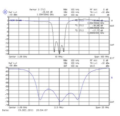
|''Narrow passband sweep'' | |||
|''Wideband sweep'' | |||
|} | |||
Latest revision as of 16:34, 15 November 2013
The Filters
Why is there even a gain when inserting additional atttenuation?
When adding a external filter, we add attenuation and degrade the noise figure, but if at the same time the bandwidth becomes less, so less atmospheric noise passes through into the receiver. One can really see that the number of frames per second raises when the filter becomes inserted while the range increases a little bit.
Here is a calculator where you can enter noise figure and bandwidth of your system. You may edit the first two lines in below table in order to see the effect of an external filter. Video-Bandwidth and Sigma are best knowledge assumptions.
The original values as I claim are:
Mode-S Beast standalone: Noise Figure 2.0 dB, RF bandwidth 30 MHz Mode-S Beast with 3 pole filter: Noise Figure 2.5 dB, RF bandwidth 13.5 MHz (see measurements below) Mode-S Beast with 5 pole filter: to be confirmed with next build
TODO ADD CALCULATOR SCRIPT
This calculation was created by my friend Luis Cupido, CT1DMK. Thanks, Luis!
Measurements of the 3 Pole Filter
I measured the 3 pole filter shown above on my own Rohde&Schwarz FSEA30 (GIF grafics) as well as on a ZVRE Vector Network analyzer (photo screenshots). The passband attenuation of 0.5dB was measured with a R&S SMPC generator and a HP436 power meter in order to have a much better accuracy.
|
| The 3 pole passband measured with R&S FSEA30 |
Measurements of the 5 Pole Filter
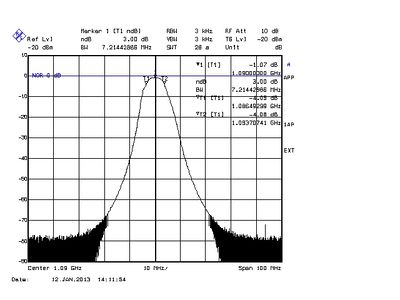
These are the measurements of the 5 pole filter. The few devices that .
|
|
| Narrow passband sweep | Wideband sweep |
