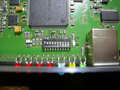
Mode-S Beast:DIP Switches
The 10 DIP switches on the component side of the PCB. Remove the brown protection with a sharp knife.
There are 10 DIP switches plus 6 solder jumpers used for configuring various optional functions of the Mode-S Beast. Currently not all of them are used and so foreseen to further extensions.
On HW V1.0 (sold around May 2011), at minimum one solder jumper is always needed at the TX-Data multiplexer:
In most cases it is the solder jumper named USB, which connects the serial output of the FPGA to the USB interface. The other possible selections are Xport (Xp) and BlueTooth (BT). Multiple connections are possible for TX-Data. The default configuration for USB is normally done before shipping.
The fallback position of the DIP switches is all off, means towards the LED: 3MBit/sec over USB, no special function activated. In case of problems with the Mode-S Beast, I always suggest falling back to this setting.
DIP Switches in the Short
| DIP | Function (if set to ON) | Recommened Setting |
| 1,2 | Baudrate between FPGA and USB interface | both OPEN |
| 3 | FW <=V1.21: AVR Format for transmission over Ethernet FW >= V1.30: Binary Format |
FW <=V1.21: OPEN FW >=V1.30: ON |
| 4 | DF11/17 filter: The Mode-S Beast only decodes DF-17 and DF-11 frames | OPEN |
| 5 | MLAT timestamp enable | ON |
| 6 | CRC check disable (for DF-11 and DF-17) | OPEN (*1) |
| 7 | DF-0/4/5 filter: The Mode-S Beast does not decode those types (mostly used when having performance problems) |
OPEN |
| 8 | RTS handshake enable | ON (see note below) |
| 9 | 1 bit forward error correction disable | OPEN (*2) |
| 10 | Mode-A/C decoding enable | ON |
(*1) Only then use DIP#6 ON position if you really know what it does.
(*2) 1 bit FEC may cause some spurious decodes of non existing aircraft because the safety of the CRC is decreased with it. If you are feeding databases, sharing networks or similar, and if this is a matter for you, disable FEC (DIP#9=ON). Otherwise, if you are just watching the air traffic, keep this switch in OPEN position in order to have as many frames as possible. Those just watching would never recognize but enjoy a bigger number of frames beeing received and enjoy some smoother traces.
Technical note: The Mode-S documents speak about even up to 5 bits beeing correctible, but when I once tried a 3 bit error correction, there were so many spuriouses that even just watching was not a pleasure. I have no idea how a true good/bad decision on these frames can be made successfully in order to make use of them.
DIP Switches in Detail
| Baudrate | SW1 | SW2 | Usage |
| 3 MBit/sec (*3) | open | open | USB serial interface (with USB over FT232R only) |
| 921600 Bit/sec (*4) | closed | open | Bluetooth interface, Lantronix Xport (Xport needs to be set to high performance mode) |
| 230400 Bit/sec | open | closed | |
| 115200 Bit/sec | closed | closed |
(*3) Until FW version V1.15 this baudrate was 1MBit/sec. It became changed to 3MBit/sec with FW Version V1.21 and later
(*4) This setting can be used when operating USB and Ethernet in parallel
Note that depending on your local traffic rate the interface baudrate is the real bottleneck of your system! So if you see a significant miss here, first introduce the DF-0/4/5 filter with DIP #7, and if that does not help, switch on DF17/DF11 filter with DIP#4. See also my comment here.
The Mode-S frames capability of the different baudrates is about:
| Baudrate | Estimated number of Mode-S frames per second maximum in UDP format |
Estimated number of Mode-S frames per second maximum in binary format |
| 3 MBit | more than 2000 | more than 4000 |
| 921600 Bit/sec | 1100 | 2200 |
| 230400 Bit/sec | 550 | 1100 |
| 115200 Bit/sec | 300 | 150 |
These are very rougth estimations!!!
Mode-AC frames are output with lower priority, so if your interface is already conguested with Mode-S frames, you will see less or no Mode-AC frames.
