Mode-S Beast:Kit Assembly
Preliminary Advice
Important note: You are handling sensitive devices here!
Ok, let me say they are not so sensitive, lets compare them to standard computer parts. I never destroyed a device at all.
Take care on electrostatic discharge, don't user plumber tools and if you have doubts, ask someone in your neighbourhood for help. Completing the kit is not complicated and I need about 30 minutes for one. So better take help from someone who knows how to handle these kind of parts instead doing it by yourselfs. If nothing helps and if you are using a directly mains connected soldering iron, disconnect it from the mains each time you solder. Taking care this time is surely worth the result.
Please also note that there are some pictures about what to do for the extra miniADSB installation on its own page.
And finally remember that there are also some solder bridges, which we set up for USB operation prior to delivery. If you need others like the Lantronix Xport or the BTM-222 Bluetooth, please read the bottom of the jumpers page.
What's in the Box
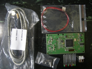
The kit contains different parts depending on the version you've ordered:
1 Channel Version
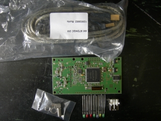
|
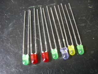
1 SMD-preassembled board "Mode-S Beast" 1 right angle female SMA connector 3 green LEDs 2 red LEDs 1 blue LED 1 yellow LED 1 USB Type B female connector 1 high quality USB cable |
2 Channel Version
(*1) Please swap the brown and black wire as shown on the miniADSB page.
I decided to deliver an USB cable as well because
- some might not have such available and
- I did see that cheap or scrappy USB cables decrease the performance. Mind that there were already issues with cheap USB cables.
How To Complete The Box Kit
SMA and the USB Connector
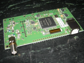
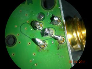
NOTE: This showed to be the most critical part for the Mode-S Beast's performance. Use as much heat as possible for the SMA. Wait for the pins to warm up, you cannot destroy something here. I saw SMA connectors that even did not get solder into the pin drills.See two photos below. If you do not burn your finger at the SMA when turing over the board after soldering, it did not get hot enougth.
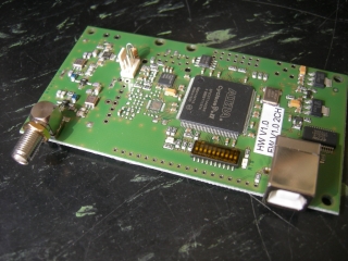
|
For the 2CH device also solder the miniADSB connector and the 33 Ohm resistor. |
Mount the Front Panel
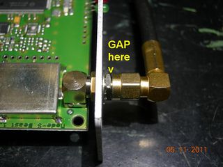
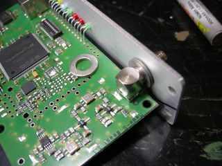
When mounting the front panel, mind that there is a small gap between a mounted SMA connector and the outer locknut, as pointed out here:
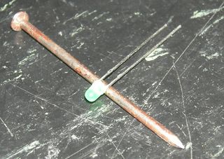
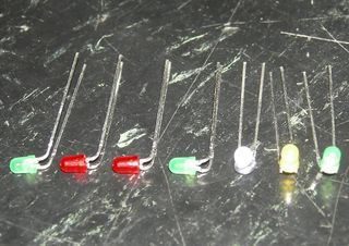
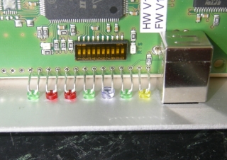
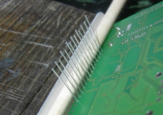
Prepare, Insert and Solder LEDs
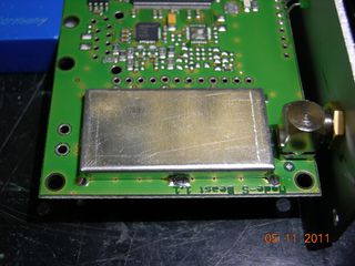
For HW V1.1 (on this photo, visible on the bottom of the PCB), mount the RX screening box.
In a few installations, there was a case sensitivity. For this purpose, we deliver a piece of black absorber foam or a piece of white absorber rubber. Locate this piece between the PCB and the box bottom.
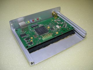
Mount the assembly into the box (picture without the RX screening box).
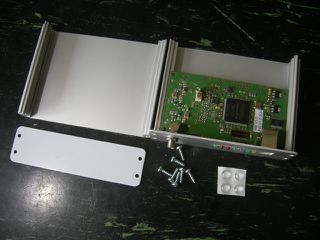
|
Mount the assembly into the box glue the 4 feet to the under side of the box |
And finally remember that there are also some solder bridges, which I set up for USB operation prior to delivery. If you need others like the Lantronix Xport or the BTM-222 Bluetooth, please read the bottom of the jumpers page.
The Mode-S Beast is now ready to be connected and tested.
Avoid These Things
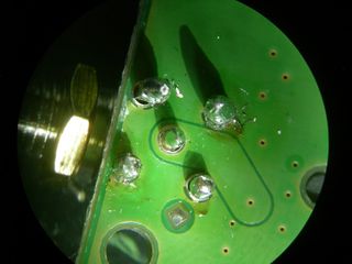
|
I got one unit back which was reported to have less performance than the unit which was used for comparison. It was due to a badly soldered SMA connector. |
|
Another bad soldering example. |
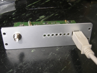
And also mind that the front panel must be mounted in a way that the SMA is higher placed than the USB and the LEDs.
