Mode-S Beast:LED Indicators
LED Indicators
Note: There is a heartbeat implemented with the LEDs: All LEDs flash for a short moment about every 1 second if there is no antenna connected. This is to inform that the unit is anyway active and working, waiting for a signal.
1CH Device, FW V1.30 or later
| DF-0, DF-4, DF-5 | DF-11 | DF-17,DF-18 | DF-20,DF-21 | Output overload |
RS232 transfer |
Power On |
2CH Device, FW V1.30 or later
| DF-11 Channel 1 |
DF-17, DF-18 Channel 1 |
DF-11 Channel 2 |
DF-17, DF-18 Channel 2 |
Output overload |
RS232 transfer |
Power On |
4CH Device, FW V1.30 or later
| DF-11, DF-17, DF-18 Channel 1 |
DF-11, DF-17, DF-18 Channel 2 |
DF-11, DF-17, DF-18 Channel 3 |
DF-11, DF-17, DF-18 Channel 4 |
Output overload |
RS232 transfer |
Power On |
Blue LED: Until FW V1.21: Small pulse each time a Mode-S frame is transfered to the internal FIFO, whatever type
since FW V1.30: FIFO overflow: the blue LED flashes each time when the output is conguested (see note)
Note: You may wonder why other devices do not indicate their output overload. It somehow has to do with the extraordinary performance of the Mode-S Beast. I also could silently drop frames if the output is overloaded, but I think it is a better way to inform the user about this situation and giving him some ways how to solve this situation: Always have DIP#8 in ON position in order to enable RTS handhake. If in FW V1.30 or later you see the blue LED flashing for longer periods, there are several ways to solve this:
- Check if your baudrate settings are as high as possible, in nearly all cases 3MBit is the recommended value
- Disable Mode-A/C decoding if you are not interested in this data, e.g. for Beamfinder and Beamfinder plus -> set DIP#10 to OPEN
- Mask all DF-0, DF-4, and DF-5 frames. These are reduandant to DF-20, DF-21 and DF-17. -> set DIP#7 to ON
- If that still does not help, only decode DF-11 and DF-17 -> set DIP#4 to ON
Heartbeat Version Control
Without input signal, various LEDs flash each second. The pattern showing up there is used to indicate the version to the user. More on the updates page.
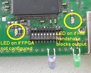
PCB mounted LEDs
FPGA configured (next to DIP switch #1): If on, it indicates that th FPGA is loaded with code. This is red for the hardware version V1.0 and will become green for later versions.
Hardware Handshake Status (next to DIP switch #10): If on, the hardware handhake prevents data to be sent to the interface. In real operation this LED should either be on for short time intervals or totally be off. It only can be on ifthe hardware handshake option is enabled with DIP #8. It is quite normal (or, better say, it should even be) that in normal operation over USB with RTS handshake enabled this LED shows very short pulses in a high frequency.
This picture has a wrong naming: the left LED is on when the FPGA is ready to operate!
